|
|
 |
STEDFA-C-PA-35-SM-B
EDFA Single Mode C-Band Standard, Wavelength 1530-1565nm, Input Power -35dBm to -25dBm, Output Power 35dBm @-35dBm input
|
|
4-6 Weeks |
$1455.00 |
|
|
|
|
STEDFA-C-PA-45-SM-B
EDFA Single Mode C-Band Standard, Wavelength 1530-1565nm, Input Power -45dBm to -25dBm, Output Power 45dBm @-45dBM input
|
|
4-6 Weeks |
$1525.00 |
|
|
|
|
STEDFA-C-BA-15-SM-B
EDFA Single Mode C-Band Booster, Wavelength 1530-1565nm, Input Power -6dBm to +3dBm, Output Power 15dBm @-3dBm input, SMF-28
|
|
4-6 Weeks |
$1103.00 |
|
|
|
|
STEDFA-C-BA-17-SM-B
EDFA Single Mode C-Band Booster, Wavelength 1530-1565nm, Input Power -6dBm to +3dBm, Output Power 17dBm @-3dBm input, SMF-28
|
|
4-6 Weeks |
$1126.00 |
|
|
|
|
STEDFA-C-BA-20-SM-B
EDFA Single Mode C-Band Booster, Wavelength 1530-1565nm, Input Power -6dBm to +3dBm, Output Power 20dBm @-3dBm input, SMF-18
|
|
4-6 Weeks |
$1197.00 |
|
|
|
|
STEDFA-C-BA-23-SM-B
EDFA Single Mode C-Band Booster, Wavelength 1530-1565nm, Input Power -6dBm to +3dBm, Output Power 23dBm @-3dBm input, SMF-28
|
|
4-6 Weeks |
$1483.00 |
|
|
|
|
STEDFA-C-BA-25-SM-B
EDFA Single Mode C-Band Booster, Wavelength 1530-1565nm, Input Power -6dBm to +3dBm, Output Power 25dBm @-3dBm input, SMF-28
|
|
4-6 Weeks |
$1899.00 |
|
|
|
|
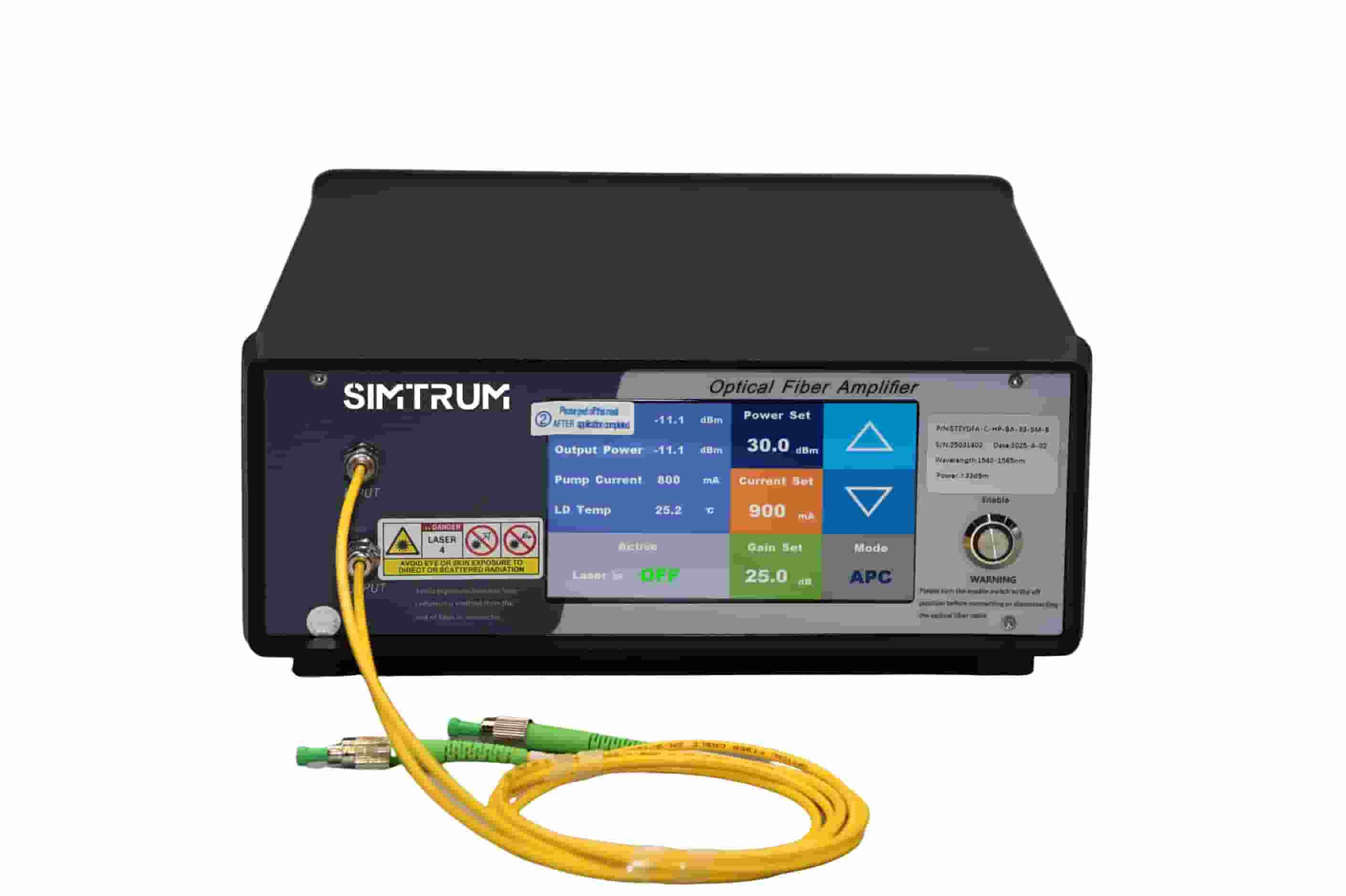
STEDFA-C-BA-26-SM-B
EDFA Single Mode C-Band Booster, Wavelength 1530-1565nm, Input Power -6dBm to +3dBm, Output Power 26dBm @-3dBm input, SMF-28
|
|
In Stock |
$2166.00 |
|