|
|
 |
STEDFA-C-HP-BA-27-SM-B
EDFA Single Mode C-Band High Power, Wavelength 1535-1565, Input Power -6dBm to +10dBm, Output Power 27dBm@-3dBm input
|
|
4-6 Weeks |
$2162.00 |
|
|
|
|
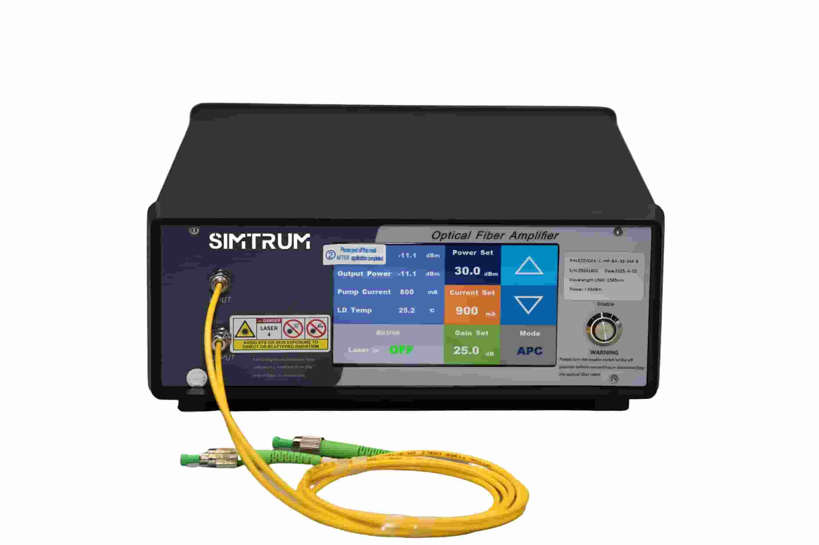
STEDFA-C-HP-BA-30-SM-B
EDFA Single Mode C-Band High Power, Wavelength 1535-1565, Input Power -6dBm to +10dBm, Output Power 30dBm@-3dBm input
|
|
4-6 Weeks |
$2209.00 |
|
|
|
|
STEDFA-C-HP-BA-33-SM-B
EDFA Single Mode C-Band High Power, Wavelength 1535-1565, Input Power -6dBm to +10dBm, Output Power 33dBm@-3dBm input
|
|
4-6 Weeks |
$2555.00 |
|
|
|
|
STEDFA-C-HP-BA-35-SM-B
EDFA Single Mode C-Band High Power, Wavelength 1535-1565nm, Input Power -6 to +10dBm, Output Power 35dBm@-3dBm input
|
|
4-6 Weeks |
$2880.00 |
|
|
|
|
STEDFA-C-HP-BA-37-SM-B
EDFA Single Mode C-Band High Power, Wavelength 1535-1565nm, Input Power -6 to +10dBm, Output Power 37dBm@-3dBm input
|
|
4-6 Weeks |
$4504.00 |
|
|
|
|
STEDFA-C-HP-BA-40-SM-B
EDFA Single Mode C-Band High Power, Wavelength 1535-1565nm, Input Power -6 to +10dBm, Output Power 40dBm@-3dBm input
|
|
4-6 Weeks |
$7536.00 |
|