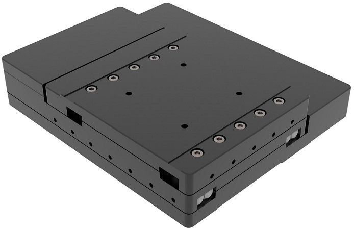
XY Motorized Piezo Stages
| Compare |
Model |
|
Drawings & Specs |
Availability |
Reference Price
(USD) |
|
|
|
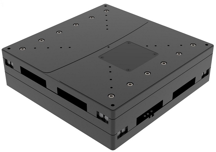 |
ST-XY4-150150
XY Motorized Piezo Stages, Stroke 150x150mm, Driver Piezoelectric Motor, Maximum Load Capacity 10KG, Maximum Speed 50mm/s, Minimum Step Size 20nm(50,100nm for option, Repeatability +/-200nm
|
|
6-8 weeks |
Request for quote |
|
|
|
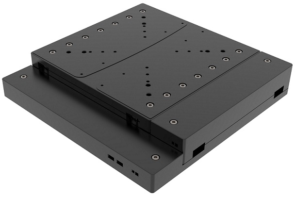 |
ST-XY3-105105
XY Motorized Piezo Stages, Stroke 150x150mm, Driver Piezoelectric Motor, Maximum Load Capacity 2KG, Maximum Speed 100mm/s, Minimum Step Size 20nm(50,100nm for option), Repeatability +/-200nm
|
|
6-8 weeks |
Request for quote |
|
|
|
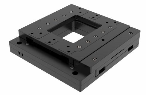 |
ST-XY3-7575
XY Motorized Piezo Stages, Stroke 75x75mm, Driver Piezoelectric Motor, Maximum Load Capacity 3KG, Maximum Speed100(Open Loop)mm/s, Minimum Step Size 50nm, Repeatability +/-200nm
|
|
6-8 weeks |
Request for quote |
|
|
|
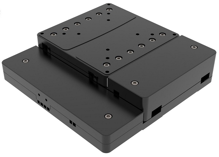 |
ST-XY3-5050
XY Motorized Piezo Stages, Stroke 50x50mm, Driver Piezoelectric Motor, Maximum Load Capacity 5KG, Maximum Speed 100mm/s, Minimum Step Size 50nm, Repeatability +/-200nm
|
|
6-8 weeks |
Request for quote |
|
|
|
 |
ST-XY2-2550
XY Motorized Piezo Stages, Stroke 50x25mm, Driver Piezoelectric Motor, Maximum Load Capacity 1KG, Maximum Speed 100mm/s, Minimum Step Size 50nm(Grating Feedback), Repeatability +/-200nm
|
|
6-8 weeks |
Request for quote |
|
ST-XY3-105105 - Parameter
ST-XY4-150150 - Parameter
Accessories
| Compare |
Model |
|
Drawings & Specs |
Availability |
Reference Price
(USD) |
|