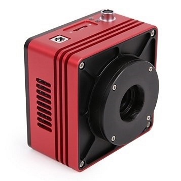
Sign In

  • Forgot your password?
  • Need a new account?

Register


Short-Wave Infrared Camera (SWIR) | SIMTRUM Photonics Store

SWIR Camera(400-1700nm) InGaAs CMOS
The SWIR series industrial cameras adopt Sony's original high-performance InGaAs CMOS sensors, with a wavelength coverage from VIS-SWIR(400-1700nm). They feature high sensitivity, wide dynamic range, and low noise.
 
These cameras support multiple high-speed data interfaces including USB3.0, GigE, 10GigE, and CXP, and are compatible with multi-platform SDKs. They are widely used in fields such as semiconductor inspection, laser imaging, biomedicine, and scientific research, where high imaging performance is required. They are the ideal choice for short-wave infrared imaging in industrial and scientific applications.
 
The main models are shown in the following table. You can choose the appropriate camera according to your specific needs.
Wavelength Range Resolution Pixel Size Data Interface Cooling
400-1700nm 5.0MP(2560*2048) 3.45um*3.45um USB 3.0
GigE
10GigE
CoaxPress
CameraLink
*Except for the USB 3.0/GigE interface which can be optionally cooled or uncooled, all other interfaces of the camera are cooled by default
3.0MP(2048*1536) 3.45um*3.45um
1.3MP(1280*1024) 5um*5um
0.33MP(640*512) 5um*5um


Features

  • High frame rate
  • Up to 14-bit ADC
  • Supports external IO trigger control
  • Precise temperature control, with a temperature difference of 10-25℃ lower than the ambient temperature

USB3/GigE/10GigE/CXP cooling camera

CameraLink cooling camera

USB3/GigE uncooling camera

5.0MP Series Model Guide
5.0MP/ (1/1.4")/3.45um × 3.45um
Model IM-TP01-5MPA/USB3 IM-TP01-5MPA/10G IM-TP01-5MPA/CXP IM-TP01-5MPA/CL IM-TP01-5MPB/USB3 IM-TP01-5MPC/UMV IM-TP01-5MPC/GMV
Sensor model Sony IMX992 - AABA - C Sony IMX992 - AABJ - C Sony IMX992 - AABJ - C
Cooling Built-in TEC cooling -25℃ External TEC cooling-10℃ Uncooling
Spectral range 400nm - 1700nm
ADC 12 Bit / 8 Bit 12 Bit / 10 Bit / 8 Bit 12 Bit / 10 Bit / 8 Bit 12 Bit / 10 Bit 12 Bit / 8 Bit 12 Bit / 8 Bit 12 Bit / 8 Bit
Frame rate & resolution 61.9fps@2560×2048 165fps@2560×2048 132fps@2560×2048 100fps@2560×2048 61.9fps@2560×2048 61.9fps@2560×2048 22fps@2560×2048
135.7fps@1280×1024 322fps@1280×1024 258fps@1280×1024 322fps@1280×1024 135.7fps@1280×1024 135.7fps@1280×1024 90fps@1280×1024
Dynamic range 51.36dB(HCG)51.47dB(LCG) 51.36dB(HCG)51.36dB(LCG) 51.36dB(HCG)51.47dB(LCG)
Max. SNR 46.17dB(HCG)48.45dB(LCG) 46.17dB(HCG)51.44dB(LCG) 46.17dB(HCG)48.45dB(LCG)
*The corresponding QE curves are presented in the Perf. Curve section.
 
3.0MP Series Model Guide
3.0MP/ (1/1.8")/3.45um × 3.45um
Model IM-TP01-3MPA/USB3 IM-TP01-3MPA/10G IM-TP01-3MPA/CXP IM-TP01-3MPA/CL IM-TP01-3MPB/USB3 IM-TP01-3MPC/UMV IM-TP01-3MPC/GMV
Sensor model Sony IMX993 - AABA - C Sony IMX993 - AABJ - C Sony IMX993 - AABJ - C
Cooling Built-in TEC cooling -25℃ External TEC cooling-10℃ Uncooling
Spectral range 400nm - 1700nm
ADC 12 Bit / 8 Bit 12 Bit / 10 Bit / 8 Bit 12 Bit / 10 Bit / 8 Bit 12 Bit / 10 Bit 12 Bit / 8 Bit 12 Bit / 8 Bit 12 Bit / 8 Bit
Frame rate & resolution 93fps@2048×1536 220fps@2048×1536 173fps@2048×1536 150fps@2048×1536 93fps@2048×1536 93fps@2048×1536 37fps@2048×1536
176fps@1024×768 415fps@1024×768 328fps@1024×768 300fps@1024×768 176fps@1024×768 176fps@1024×768 148fps@1024×768
Dynamic range 51.36dB(HCG)51.47dB(LCG) 51.36dB(HCG)51.36dB(LCG) 51.36dB(HCG)51.47dB(LCG)
Max. SNR 46.17dB(HCG)48.45dB(LCG) 46.17dB(HCG)51.44dB(LCG) 46.17dB(HCG)48.45dB(LCG)

*The corresponding QE curves are presented in the Perf. Curve section.

 
5.0/3.0MP general parameter table
Model xxMPA/USB3 xxMPA/10G xxMPA/CXP xxMPA/CL xxMPB/USB3 xxMPC/UMV xxMPC/GMV
Hardware image cache 512MByte
Conversion gain 10.3e/ADU(HCG)17.29e/ADU(LCG)
Dynamic range 51.36dB(HCG)51.47dB(LCG) 51.36dB(HCG)
51.36dB(LCG)
51.36dB(HCG)51.47dB(LCG)
Readout noise 111.88e(HCG)186.61e(LCG)
Full well charge 41.39ke(HCG)69.92ke(LCG)
Max. SNR 46.17dB(HCG)48.45dB(LCG) 46.17dB(HCG)
51.44dB(LCG)
46.17dB(HCG)48.45dB(LCG)
Gain Span 1x - 15x
Exposure time 15μs - 60s
Shutter mode Global shutter
Binning mode software 2×2, 3×3, 4×4 Not supported software 2×2, 3×3, 4×4
Data interface USB3 GigE CoaxPress Cameralink USB3 USB3 GigE
Digital IO One optocoupler isolated input, one optocoupler isolated output, and two non-isolated input and output ports
Data format 8bit / 12bit 10bit / 12bit 8bit / 12bit 8bit / 12bit 8bit / 12bit
Cooling temperature difference Below room temperature 25°C Below room temperature 10°C uncooling
Filter 400 - 1800nm(Standard configuration);1030 - 1800nm(Optional)
CRA 2.35 °
Power supply Power supply via USB3 interface /12V power adapter Power supply by 12V power adapter Power supply via USB3 interface / 12V power adapter Power supply via USB3 interface Power supply by 12V power adapter
Power consumption 2.1Wuncooling /
25Wcooling
/

2.1Wuncooling / 
25Wcooling

<2.11W <2.11W
Temperature Operating temperature -20~60°C,Storage temperature -40~85°C
Humidity 20% - 80%,No condensation
Size/Weight 80mm×80mm×45.5mm/<390g 75mm×75mm×81.9mm/<390g 80mm×80mm×45.5mm/<390g 33mm×33mm×38mm/70g 33mm×33mm×58mm
Lens interface C interface
Software A complete SDK development package/TpView A complete SDK development package/CLView A complete SDK development package/TpView
Operating system Win32/WinRT/Linux/macOS/Android
Certification CE,FCC

Note: HCG(High Conversion Gain) refers to the high conversion gain mode. It usually enhances the signal at the stage when the noise is relatively small right after the optical signal is converted into an electrical signal, so that the noise generated later is relatively small. Thus, even in dim conditions, low-noise images can be captured, thereby improving the recognition accuracy. Under bright conditions that emphasize dynamic range, the LCG mode can be switched.

5.0MP Series Camera(IMX992 ) QE Curve
3.0MP Series Camera (IMX993) QE Curve

 
The SWIR series cameras mainly use two types of filters: long-pass filters LPF390H and LP1000H. The transmittance curves of the two filters are as follows:
The transmittance curve of LPF390H: Cut-off at 200-375nm and transmission at 400-1800nm.
 
 
The transmittance curve of LP1000H: Cut-off at 200-980nm, transmission at 1030-1800nm.
 

1.3MP Series Model Guide
1.3MP/ (1/1.2")/5um × 5um
Model IM-TP01-1.3MPA/USB3 IM-TP01-1.3MPA/G IM-TP01-1.3MPA/CXP IM-TP01-1.3MPA/CL IM-TP01-1.3MPB/USB3 IM-TP01-1.3MPB/G IM-TP01-1.3MPC/UMV IM-TP01-1.3MPC/GMV
Sensor model Sony IMX990 - AABA - C Sony IMX990 - AABJ - C Sony IMX990 - AABJ - C
Cooling Built-in TEC cooling -25℃ External TEC cooling-10℃ Uncooling
Spectral range 400nm - 1700nm
ADC 12 Bit / 8 Bit 12 Bit / 8 Bit 12 Bit / 8 Bit 12 Bit / 8 Bit 12 Bit / 8 Bit 12 Bit / 8 Bit 12 Bit / 8 Bit 12 Bit / 8 Bit
Frame rate & resolution 200fps@1280×1024 90fps@1280×1024 200fps@1280×1024 200fps@1280×1024 200fps@1280×1024 90fps@1280×1024 223fps@1280×1024 90fps@1280×1024
392fps@640×512 253fps@640×512 392fps@640×512 392fps@640×512 392fps@640×512 253fps@640×512 428fps@640×512 253fps@640×512
Dynamic range 58.7dB
Max. SNR 52.6dB 52.4dB
 
0.33MP Series Model Guide
0.33MP/ (1/1.4")/5um × 5um
Model IM-TP01-0.33MPA/USB3 IM-TP01-0.33MPA/G IM-TP01-0.33MPA/CXP IM-TP01-0.33MPA/CL IM-TP01-0.33MPB/USB3 IM-TP01-0.33MPB/G IM-TP01-0.33MPC/UMV IM-TP01-0.33MPC/GMV
Sensor model Sony IMX991 - AABA - C Sony IMX991 - AABJ - C Sony IMX991 - AABJ - C
Cooling Built-in TEC cooling -25℃ External TEC cooling-10℃ Uncooling
Spectral range 400nm - 1700nm
ADC 12 Bit / 8 Bit 12 Bit / 8 Bit 12 Bit / 8 Bit 12 Bit / 8 Bit 12 Bit / 8 Bit 12 Bit / 8 Bit 12 Bit / 8 Bit 12 Bit / 8 Bit
Frame rate & resolution 400fps@640×512 257.8fps@640×512 400fps@640×512 400fps@640×512 400fps@640×512 257.8fps@640×512 428.1fps@640×512 257.8fps@640×512
753fps@320×256 486.1fps@320×256 753fps@320×256 753fps@320×256 753fps@320×256 486.1fps@320×256 807fps@320×256 486.1fps@320×256
Dynamic range 58.7dB
Max. SNR 52.6dB 52.4dB


1.3/0.33MP general parameter table

Model xxMPA/USB3 xxMPA/G xxMPA/CXP xxMPA/CL xxMPB/USB3 xxMPB/G xxMPC/UMV xxMPC/GMV
Hardware image cache 512MByte
Conversion gain 44.3e/ADU 42.8e/ADU
Dynamic range 58.7dB
Readout noise 211e 197.6e
Full well charge 181.6ke 175.4ke
Max. SNR 52.6dB 52.4dB
Sensitivity 121mV
Dark current 383e/s(0°C) 510e/s(10°C) 638e/s(20°C) 638e/s(20°C)
Gain span 1x - 15x
Exposure time 15μs - 60s
Shutter mode Global shutter
Binning mode software 2×2, 3×3, 4×4 not support software 2×2, 3×3, 4×4
Data interface USB3 GigE CoaxPress Cameralink USB3 GigE USB3 GigE
Digital IO One optocoupler isolated input, one optocoupler isolated output, and two non-isolated input and output ports
Data format 8bit / 12bit
Cooling temperature difference Below room temperature 25°C Below room temperature 10°C uncooling
Filter 400 - 1800nm(Standard configuration);1030 - 1800nm(Optional)
CRA 2.35 °
Power supply Power supply via USB3 interface / 12V power adapter Power supply by 12V power adapter Power supply via USB3 interface /
 12V power adapter
Power supply by 12V power adapter Power supply via USB3 interface Power supply by 12V power adapter
Power consumption <2.1W(uncooling) / <25W(cooling) <2.11W
Temperature Operating temperature -20~60°C,Storage temperature -40~85°C
Humidity 20% - 80%,No condensation
Size/Weight 80mm×80mm×45.5mm/<390g 75mm×75mm×81.9mm/<390g 80mm×80mm×45.5mm/<390g 33mm×33mm×38mm/70g 33mm×33mm×58mm
Lens interface C interface
Software A complete SDK development package/TpView A complete SDK development package/CLView A complete SDK development package/TpView
Operating system Win32/WinRT/Linux/macOS/Android
Certification CE,FCC


1.3MP Series Camera (IMX990) QE Curve
0.33MP Series Camera (IMX991) QE Curve
 
The SWIR series cameras mainly use two types of filters: long-pass filters LPF390H and LP1000H. The transmittance curves of the two filters are as follows:
The transmittance curve of LPF390H: Cut-off at 200-375nm and transmission at 400-1800nm.
 
 
The transmittance curve of LP1000H: Cut-off at 200-980nm, transmission at 1030-1800nm.
 

USB interface cooling camera


Details of the USB3 cooling camera interface


Num Details 

1,USB3 interface 
2,DC 12V Power interface 
3,External IO port 

GigE interface cooling camera

 
Details of the GigE cooling camera interface

Num Details 

1,GigE inetrface
2,DC 12V Power interface 
3,External IO port 

CameraLink interface cooling camera

Details of the CameraLink cooling camera interface
 
Num Details 
  1. 1,External IO port 
  2. 2,DC 12V Power interface 
  3. 3,CameraLink1 
  4. 4,CameraLink2 

USB interface uncooling camera

Details of the USB uncooling camera interface
Num Details 
  1. 1 USB interface
  2. 2 External IO port


USB cooling camera packing diagram and packing list
Num Details
A Outer box B (not shown in the figure) dimensions of the outer packaging carton: L: 28.2cm, W: 25.2cm, H: 16.7cm
B 3-A Instrument Safety Box: L: 28cm, W: 23.0cm, H: 15.5cm (1 piece, 2.8Kg per box)
C USB cooling camera
D Power cords are available in national standard, American standard, European standard and British standard (D1, D2, D3, D4 are not shown in the figure).
E Power adapter: Input: AC 100-240V 50Hz/60Hz, Output: DC 12V 3A
F High-speed USB3 A male to B male gold-plated head data cable /1.5m
G One external trigger control line
H Usb flash drive (containing drivers and application software)

GigE cooling camera packing diagram and packing list
Num Details
A Outer box B (not shown in the figure) dimensions of the outer packaging carton: L: 28.2cm, W: 25.2cm, H: 16.7cm
B 3-A Instrument Safety Box: L: 28cm, W: 23.0cm, H: 15.5cm (1 piece, 2.8Kg per box)
C GigE cooling camera
D Power cords are available in national standard, American standard, European standard and British standard (D1, D2, D3, D4, not shown in the figure).
E Power adapter: Input: AC 100-240V 50Hz/60Hz, Output: DC 12V 3A
F One external trigger control line
G Network cable: G1:3m, G2:5m, G3:10m (G4:50m is not shown in the figure)
H Usb flash drive (containing drivers and application software)

CoaxPress cooling camera packing diagram and packing list
Num Detail
A Outer box B (not shown in the figure) dimensions of the outer packaging carton: L: 28.2cm, W: 25.2cm, H: 16.7cm
B 3-A Instrument Safety Box: L: 28cm, W: 23.0cm, H: 15.5cm (1 piece, 2.8Kg per box)
C CoaxPress cooling camera
D Power cords are available in national standard, American standard, European standard and British standard (D1, D2, D3, D4, not shown in the figure).
E Power adapter: Input: AC 100-240V 50Hz/60Hz, Output: DC 12V 3A
F One CoaxPress cable
G One external trigger control line
H Usb flash drive (containing drivers and application software)

CameraLink cooling camera packing diagram and packing list
Num Details
A 3-A Instrument Safety Box: L: 28cm, W: 23.0cm, H: 15.5cm (1 piece, 2.8Kg per box)
B CL cooling camera
C 2 CameraLink wires
D 12V/3A 6-pin aviation power adapter
E Power cord
F One external trigger control line

USB uncooling camera packing diagram and packing list
Num Details
A Outer box B (not shown in the figure) dimensions of the outer packaging carton: L: 28.2cm, W: 25.2cm, H: 16.7cm
B 3-A Instrument Safety Box: L: 28cm, W: 23.0cm, H: 15.5cm (1 piece, 2.8Kg per box)
C USB uncooling camera
D High-speed USB3 A male to B male gold-plated head data cable /1.5m
E One external trigger control line
F USB flash drive (containing drivers and application software)

Pin definition

Table 1. Pin Signal Definitions for USB/GigE and CameraLink Interface cooling cameras


Color Pin Signal Details
white 1 GDN Non-isolated signal and power ground
red 2 12V 12VDC power input
blue 3 OPTO_GND The optocoupler isolates the signal ground
yellow 4 DIR_GPIO0 Non-isolated signal (software-configurable input/output) (line2)
black 5 DIR_GPIO1 Non-isolated signal (software-configurable input/output) (line3)
green 6 OPTO_IN Optocoupler isolated input signal (line0)
pink 7 OPTO_OUT Optocoupler isolated output signal (line1)


Table 2. Pin Signal Definitions for USB Interface uncooling(UMV) cameras
Color Pin Signal Details
white 1 DIR_GPIO Non-isolated signal (software-configurable input/output) (line2)
red 2 OPTO_GND The optocoupler isolates the signal ground
blue 3 OPTO_OUT Optocoupler isolated output signal (line1)
green 4 OPTO_IN Optocoupler isolated input signal (line0)
black 5 GND Non-isolated signal and power ground
yellow 6 5V 5VDC power input


I/O electrical characteristics

1. Optocoupler isolated input circuit (line0)

In the I/O control of the camera, the optocoupler isolation input circuit is shown in the following figure.

Fig 1.Optocoupler input circuit

Logic 0 input level: 0~2.2VDC(OPTO_IN pin)

Logic 1 input level: 3.3-24VDC(OPTO_IN pin)

Maximum input current: 30mA

The circuit operation state is unstable when the input level is between 2.2 and 3.2V. Please try to avoid operating the input voltage within this range.

Fig 2.Input logic level

Input rise delay (TDR) : 6us

Input drop delay (TDF) : 6us


2.Optocoupler isolated output circuit (line1)

In the camera I/O control, the optocoupler isolated output circuit is shown in Figure 3.

Fig3.optocoupler isolated output circuit

The maximum output current of the optocoupler isolation is 30mA.

Fig 4.Output logic level


The electrical characteristics of the isolated output of the optocoupler (external voltage 5V, external resistance 1K) are shown in Table 3 below.

Tab 3.Electrical characteristics of optocoupler isolated output

Parameter Symbol Value
Output logic low level VL 742mV
Output logic high level VH 4.134V
Output rise time TR 4us
Output drop time TF 1.8us
Output rise delay TDR 12us
Output drop delay TDF 2us


The corresponding current and logic low-level parameters of the optocoupler isolated output when different voltages and resistors are used externally are shown in Table 4.

Tab 4.The optocoupler isolates the output logic low-level parameters

External voltage External resistance VL Output current
3.3V 1KΩ 510mV 2.82mA
5V 1KΩ 742mV 4.31mA
12V 2.4KΩ 795mV 4.68mA
24V 4.7KΩ 850mV 4.97mA


3. Input/Output I/O circuits (line2/line3)

The non-isolated configurable input/output I/O circuit is shown in Figure 5/6.

Fig 5. Non-isolated Configurable Input/Output I/O Circuit (line2)

Fig 6. Non-isolated Configurable Input/Output I/O Circuit (line3)

• Line2/line3 set as input pins:

Logic 0 input level: 0 to 0.6VDC(pins DIR_GPIO1/DIR_GPIO2)

Logic 1 input level: 2.0-24VDC(DIR_GPIO1/DIR_GPIO2 pins)

Maximum input current: 25mA

The circuit operation state is unstable when the input level is between 0.6 and 2.0V. Please try to avoid operating the input voltage within this range.

Fig 7.Input logic level

To prevent damage to the GPIO pins, please connect the pin GND first, and then input voltage to the Line2 pin.

Input rise delay (TDR) : 0.02us

Input drop delay (TDF) : 0.02us


• Set Line2/line3 as output pins:

The maximum current allowed through this pin is 25mA.

The external temperature is 25 ° C, and the relationship between external voltage, resistance and output low level is shown in Table 5 below.

Tab 5.Non-isolated output logic low-level parameters

External voltage External resistance VL (GPIO)
3.3V 1KΩ 0.11V
5V 1KΩ 0.167V
12V 2.4KΩ 0.184V
24V 4.7KΩ 0.385V


The external pull-up voltage is 5V and the pull-up resistor is 1KΩ. The GPIO configuration sets the output logic level and electrical characteristics as shown in Figure 8.

Fig 8.Output logic level


Tab 6.Non-isolated output electrical characteristics

Parameter Symbol Value
Output rise time TR 0.08us
Output drop time TF 0.02us
Output rise delay TDR 0.1us
Output drop delay TDF 0.04us


You can log in to our official website to obtain the latest software installation package. This series can be used together with ASCOM and DirectShow SDKS. If the third-party software is compatible with these SDKS, you can also download the driver from our website and install it in the third-party software.

This software is a professional one integrating functions such as camera control, image acquisition and processing, image browsing and analysis. It has the following characteristics:

  • x86: XP SP3 and above; The CPU supports SSE2 and above
  • x64: Windows 7 and above
  • Supports video mode and trigger mode (Raw format or RGB format)
  • Automatic capture and quick recording function
  • Supports multiple languages
  • Hardware ROI and digital binning functions
  • Rich image processing functions, such as image stitching, real-time overlay, flat field correction, dark field correction, etc
  •  

Software interface


Introduction to the functions of the camera control panel

Function Description
Capture and resolution Set real-time and static capture, snapshot images or video recording
Exposure and Gain Automatic exposure (preset exposure target value), manual exposure (exposure time can be manually entered and set with a slider); The gain is up to 5 times
White balance Advanced one-click intelligent white balance setting, and you can also manually adjust the white balance by setting the color temperature and color
Color adjustment Initial high-speed adjustment function for color, saturation, brightness, contrast and gamma value
Frame rate control For different computers and USB performance, super compatibility with cameras can be achieved by adjusting the frame rate
Flip Selecting "horizontal" or "vertical" can adjust the sample direction to ensure it is consistent with the visual system direction
Sampling Neighborhood averaging can improve the signal-to-noise ratio of video streams. The sampling extraction mode can ensure the sharpness of the video stream. Support histogram expansion of video streams, switching between negative and positive images, grayscale calibration, and calculation of clarity factors to facilitate video focusing
Bit depth 8. 12-bit switching, with 8-bit being the basic Windows image format. 12-bit has higher image quality, but it will reduce the frame rate
ROI The ROI, Region of interest function can set the ROI value of the video window. After the ROI group is expanded, a rectangular box will appear in the middle of the video window, through which the ROI can be changed. The size of the ROI can be adjusted with the mouse. If there is no issue with the ROI, click "Apply" to set the video to the ROI size. The default value will be restored to the original size
Dark field correction To Enable dark field correction, you should first capture the narrow-field image and then click Enable. Selecting "Enable" will enable dark field correction. Not selecting it will disable dark field correction
cooling Set the TEC target temperature and the fan on/off
Parameter saving Load, save, overwrite, load, export custom camera panel control (including calibration information, exposure parameters and color setting information, etc.
 
 
Introduction to Image processing functions
Function Description
Video function A variety of professional video processing functions: video broadcasting, timed capture, video recording, video watermarking, watermark movement alignment, watermark rotation alignment, video grid overlay, video measurement, video calibration, grayscale calibration, video high dynamic range (HDR), video depth of field expansion, video image stitching, video scale, date, etc. overlay
Image processing and enhancement Image contrast control and adjustment, image denoising, various image filtering algorithms, image mathematical morphology algorithms, image rotation, image scaling and image printing, etc
Image superposition The TPView image overlay denoising function introduces advanced image matching technology. Users only need to record a short video of the image they want to overlay, and they can overlay and output high-fidelity images even when there are displacement, rotation, and magnification changes among multiple frames of the video. It is simple and easy to use

Example of image overlay denoising function


*For more instructions on the use and configuration of the software, please refer to the user manual.


We are here for you!


Drop us an email at info@simtrum.com to get the Best Price today.   Want more technical information? Click Here for the professional Customized System/ Solutions.


Don't have time to search the products one by one? No worries. you can download the full range of SIMTRUM Product Line Cards.

Click it now.


Want to stay closer to the Market Dynamics and Technological 

Developments? Just take 5 seconds to Sign In as a member of 

SIMTRUM, we will bring you the most up-to-date news. 

(Sign in button on the top right of the screen).


Search Reset
Compare Model Drawings & Specs Availability Reference Price
(USD)
IM-TP01-5MPA/USB3
Resolution:2560*2048(5.0MP),Frame:61.9fps@2560×2048/135.7fps@1280×1024,Dynamic Range:51.36dB(HCG)/51.47dB(LCG),Readout Noise:111.88e(HCG),186.61e(LCG),Data Interface:USB3.0
4-6 Weeks Request for quote
IM-TP01-5MPA/10G
Resolution:2560*2048(5.0MP),Frame:165fps@2560x2048 /322fps@1280x1024,Dynamic Range:51.36dB(HCG)/51.47dB(LCG),Readout Noise:111.88e(HCG),186.61e(LCG),Data Interface:10GigE
4-6 Weeks Request for quote
IM-TP01-5MPA/CXP
Resolution:2560*2048(5.0MP),Frame:132fps@2560×2048/258fps@1280×1024,Dynamic Range:51.36dB(HCG)/51.47dB(LCG),Readout Noise:111.88e(HCG),186.61e(LCG),Data Interface:Coaxpress
4-6 Weeks Request for quote
IM-TP01-5MPA/CL
Resolution:2560*2048(5.0MP),Frame:100fps@2560×2048/322fps@1280×1024,Dynamic Range:51.36dB(HCG)/51.47dB(LCG),Readout Noise:111.88e(HCG),186.61e(LCG),Data Interface:CameraLink
4-6 Weeks Request for quote
IM-TP01- 5MPB/USB3
Resolution:2560*2048(5.0MP),Frame:61.9fps@2560×2048/135.7fps@1280×1024,Dynamic Range:51.36dB(HCG)/51.47dB(LCG),Readout Noise:111.88e(HCG),186.61e(LCG),Data Interface:USB3.0
4-6 Weeks Request for quote
IM-TP01- 5MPC/UMV
Resolution:2560*2048(5.0MP),Frame:61.9fps@2560×2048/135.7fps@1280×1024,Dynamic Range:51.36dB(HCG)/51.47dB(LCG),Readout Noise:111.88e(HCG),186.61e(LCG),Data Interface:USB3.0
4-6 Weeks Request for quote
IM-TP01- 5MPC/GMV
Resolution:2560*2048(5.0MP),Frame:22fps@2560×2048/90fps@1280×1024,Dynamic Range:51.36dB(HCG)/51.47dB(LCG),Readout Noise:111.88e(HCG),186.61e(LCG),Data Interface:GigE
4-6 Weeks Request for quote
IM-TP01-3MPA/USB3
Resolution:2048*1536(3.0MP),Frame:93fps@2048×1536/176fps@1024×768,Dynamic Range:51.36dB(HCG)/51.47dB(LCG),Readout Noise:111.88e(HCG),186.61e(LCG),Data Interface:USB3.0
4-6 Weeks Request for quote
IM-TP01-3MPA/10G
Resolution:2048*1536(3.0MP),Frame:220fps@2048×1536/415fps@1024×768,Dynamic Range:51.36dB(HCG)/51.47dB(LCG),Readout Noise:111.88e(HCG),186.61e(LCG),Data Interface:10GigE
4-6 Weeks Request for quote
IM-TP01-3MPA/CXP
Resolution:2048*1536(3.0MP),Frame:173fps@2048×1536/328fps@1024×768,Dynamic Range:51.36dB(HCG)/51.47dB(LCG),Readout Noise:111.88e(HCG),186.61e(LCG),Data Interface:Coaxpress
4-6 Weeks Request for quote
IM-TP01-3MPA/CL
Resolution:2048*1536(3.0MP),Frame:150fps@2048×1536/300fps@1024×768,Dynamic Range:51.36dB(HCG)/51.47dB(LCG),Readout Noise:111.88e(HCG),186.61e(LCG),Data Interface:CameraLink
4-6 Weeks Request for quote
IM-TP01-3MPB/USB3
Resolution:2048*1536(3.0MP),Frame:93fps@2048×1536/176fps@1024×768,Dynamic Range:51.36dB(HCG)/51.47dB(LCG),Readout Noise:111.88e(HCG),186.61e(LCG),Data Interface:USB3.0
4-6 Weeks Request for quote
IM-TP01-3MPC/UMV
Resolution:2048*1536(3.0MP),Frame:93fps@2048×1536/176fps@1024×768,Dynamic Range:51.36dB(HCG)/51.47dB(LCG),Readout Noise:111.88e(HCG),186.61e(LCG),Data Interface:USB3.0
4-6 Weeks Request for quote
IM-TP01-3MPC/GMV
Resolution:2048*1536(3.0MP),Frame:37fps@2048×1536/148fps@1024×768,Dynamic Range:51.36dB(HCG)/51.47dB(LCG),Readout Noise:111.88e(HCG),186.61e(LCG),Data Interface:GigE
4-6 Weeks Request for quote
IM-TP01-1.3MPA/USB3
Resolution:1280*1024(1.3MP),Frame:200fps@1280×1024/392fps@640×512,Dynamic Range:58.7dB,Readout Noise:211e,Data Interface:USB3.0
4-6 Weeks Request for quote
IM-TP01-1.3MPA/G
Resolution:1280*1024(1.3MP),Frame:90fps@1280×1024/253fps@640×512,Dynamic Range:58.7dB,Readout Noise:211e,Data Interface:GigE
4-6 Weeks Request for quote
IM-TP01-1.3MPA/CXP
Resolution:1280*1024(1.3MP),Frame:200fps@1280×1024/392fps@640×512,Dynamic Range:58.7dB,Readout Noise:211e,Data Interface:Coaxpress
4-6 Weeks Request for quote
IM-TP01-1.3MPA/CL
Resolution:1280*1024(1.3MP),Frame:200fps@1280×1024/392fps@640×512,Dynamic Range:58.7dB,Readout Noise:211e,Data Interface:CameraLink
4-6 Weeks Request for quote
IM-TP01-1.3MPB/USB3
Resolution:1280*1024(1.3MP),Frame:200fps@1280×1024/392fps@640×512,Dynamic Range:58.7dB,Readout Noise:197.6e,Data Interface:USB3.0
4-6 Weeks Request for quote
IM-TP01-1.3MPB/G
Resolution:1280*1024(1.3MP),Frame:90fps@1280×1024/253fps@640×512,Dynamic Range:58.7dB,Readout Noise:197.6e,Data Interface:GigE
4-6 Weeks Request for quote
IM-TP01-1.3MPC/UMV
Resolution:1280*1024(1.3MP),Frame:223fps@1280×1024/428fps@640×512,Dynamic Range:58.7dB,Readout Noise:197.6e,Data Interface:USB3.0
4-6 Weeks Request for quote
IM-TP01-1.3MPC/GMV
Resolution:1280*1024(1.3MP),Frame:90fps@1280×1024/253fps@640×512,Dynamic Range:58.7dB,Readout Noise:197.6e,Data Interface:GigE
4-6 Weeks Request for quote
IM-TP01-0.33MPA/USB3
Resolution:640*512(0.33MP),Frame:400fps@640×512/753fps@320×256,Dynamic Range:58.7dB,Readout Noise:211e,Data Interface:USB3.0
4-6 Weeks Request for quote
IM-TP01-0.33MPA/G
Resolution:640*512(0.33MP),Frame:257.8fps@640×512/486.1fps@320×256,Dynamic Range:58.7dB,Readout Noise:211e,Data Interface:GigE
4-6 Weeks Request for quote
IM-TP01-0.33MPA/CXP
Resolution:640*512(0.33MP),Frame:400fps@640×512/753fps@320×256,Dynamic Range:58.7dB,Readout Noise:211e,Data Interface:Coaxpress
4-6 Weeks Request for quote
IM-TP01-0.33MPA/CL
Resolution:640*512(0.33MP),Frame:400fps@640×512/753fps@320×256,Dynamic Range:58.7dB,Readout Noise:211e,Data Interface:CameraLink
4-6 Weeks Request for quote
IM-TP01-0.33MPB/USB3
Resolution:640*512(0.33MP),Frame:400fps@640×512/753fps@320×256,Dynamic Range:58.7dB,Readout Noise:197.6e,Data Interface:USB3.0
4-6 Weeks Request for quote
IM-TP01-0.33MPB/G
Resolution:640*512(0.33MP),Frame:257.8fps@640×512/486.1fps@320×256,Dynamic Range:58.7dB,Readout Noise:197.6e,Data Interface:GigE
4-6 Weeks Request for quote
IM-TP01-0.33MPC/UMV
Resolution:640*512(0.33MP),Frame:428.1fps@640×512/807fps@320×256,Dynamic Range:58.7dB,Readout Noise:197.6e,Data Interface:USB3.0
4-6 Weeks Request for quote
IM-TP01-0.33MPC/GMV
Resolution:640*512(0.33MP),Frame:257.8fps@640×512/486.1fps@320×256,Dynamic Range:58.7dB,Readout Noise:197.6e,Data Interface:GigE
4-6 Weeks Request for quote

IM-TP01-0.33MPC/GMV - Parameter

IM-TP01-0.33MPC/UMV - Parameter

IM-TP01-0.33MPB/G - Parameter

IM-TP01-0.33MPB/USB3 - Parameter

IM-TP01-0.33MPA/CL - Parameter

IM-TP01-0.33MPA/CXP - Parameter

IM-TP01-0.33MPA/G - Parameter

IM-TP01-0.33MPA/USB3 - Parameter

IM-TP01-1.3MPC/GMV - Parameter

IM-TP01-1.3MPC/UMV - Parameter

IM-TP01-1.3MPB/G - Parameter

IM-TP01-1.3MPB/USB3 - Parameter

IM-TP01-1.3MPA/CL - Parameter

IM-TP01-1.3MPA/CXP - Parameter

IM-TP01-1.3MPA/G - Parameter

IM-TP01-1.3MPA/USB3 - Parameter

IM-TP01-3MPC/GMV - Parameter

IM-TP01-3MPC/UMV - Parameter

IM-TP01-3MPB/USB3 - Parameter

IM-TP01-3MPA/CL - Parameter

IM-TP01-3MPA/CXP - Parameter

IM-TP01-3MPA/10G - Parameter

IM-TP01-3MPA/USB3 - Parameter

IM-TP01- 5MPC/GMV - Parameter

IM-TP01- 5MPC/UMV - Parameter

IM-TP01- 5MPB/USB3 - Parameter

IM-TP01-5MPA/CL - Parameter

IM-TP01-5MPA/CXP - Parameter

IM-TP01-5MPA/10G - Parameter

IM-TP01-5MPA/USB3 - Parameter

IM-TP01-0.33MPC/GMV - Download

IM-TP01-0.33MPC/UMV - Download

IM-TP01-0.33MPB/G - Download

IM-TP01-0.33MPB/USB3 - Download

IM-TP01-0.33MPA/CL - Download

IM-TP01-0.33MPA/CXP - Download

IM-TP01-0.33MPA/G - Download

IM-TP01-0.33MPA/USB3 - Download

IM-TP01-1.3MPC/GMV - Download

IM-TP01-1.3MPC/UMV - Download

IM-TP01-1.3MPB/G - Download

IM-TP01-1.3MPB/USB3 - Download

IM-TP01-1.3MPA/CL - Download

IM-TP01-1.3MPA/CXP - Download

IM-TP01-1.3MPA/G - Download

IM-TP01-1.3MPA/USB3 - Download

IM-TP01-3MPC/GMV - Download

IM-TP01-3MPC/UMV - Download

IM-TP01-3MPB/USB3 - Download

IM-TP01-3MPA/CL - Download

IM-TP01-3MPA/CXP - Download

IM-TP01-3MPA/10G - Download

IM-TP01-3MPA/USB3 - Download

IM-TP01- 5MPC/GMV - Download

IM-TP01- 5MPC/UMV - Download

IM-TP01- 5MPB/USB3 - Download

IM-TP01-5MPA/CL - Download

IM-TP01-5MPA/CXP - Download

IM-TP01-5MPA/10G - Download

IM-TP01-5MPA/USB3 - Download

Accessories

Compare Model Drawings & Specs Availability Reference Price
(USD)