Confocal Raman Microscope
Handheld Confocal Raman Skin Analyzer
Spinning Disk Confocal Microscope
Laser Point Scanning Confocal Microscope
Research Line Scan Confocal Microscope
Industry Line Scan Confocal Microscope
More
Auto-Fluorescence Microscope
Compact Multi-channel fluorescence microscope Module
Four-channel Single-mode /Multi-mode laser(405-640 nm)
Silicon photomultiplier(SIPM)(300-950nm)
Photomultiplier Tube (Module)(160-900nm)
Motorized Filter Wheels
TCSPC System for SPAD (APD) Testing Solution
Fiber Spectrometers (200nm to 2.5um)
Raman Spectrometer 532/785/1064nm
X-Ray/XUV/VUV Spectrometers (1-300nm)
FT Infrared Spectrometer(900-16000nm)
Hyperspectral Camera (220nm-12.5μm)
Multi-Spectral Camera (400-1000nm)
Single Photon Detector (SPD)(200-1700nm)
Photomultiplier Tubes (PMT)(160-900nm)
Photodiode Detector (PD)(320-1700nm)
Pyroelectric Infrared Detectors (2-12um)
Single-Photon Avalanche Diode Array
UV-VIS Beam Profiler(190-1100nm)
VIS-NIR Beam Profiler(350-1750nm)
Mid-infrared Beam Profiler(2-16μm)
Compact Beam Profiler(190-1100nm)
Terahertz Beam Profiler
Scanning Slit Beam Profiler
Photodiode Power Sensors 250-2500nm
Power Meter Console
Integrating Spheres (10mm-100mm)
Power Meter Adaptor & Accessories
Thermoelectric laser power meter(0.19-25 μm)
Photoelectric power meter(200-1100nm)
VUV/UV Spectrograph
Standard Single Grating Monochromator
Hi-Res Single Grating Monochromator
Double Grating Scanning Monochromator
Triple Grating Scanning Monochromator
Hi-Res Triple Grating Monochromator
Micro laser Doppler vibrometer DC~2.5MHz
Laser Doppler Vibrometer 0.1Hz to 5Mhz
LIV Test Systems for Laser Diode / LED
White Light Interferometer
Optical Test Measurement System
RF Test Measurement System
Point confocal displacement sensor
Linear confocal displacement sensor
CW Pigtail Laser Diode (400-1920nm)
CW Laser Diode Module (375-785nm)
CW Multi-Channel Lasers (375-808nm)
CW Narrow Linewidth Diode Laser
External Cavity Tunable Diode Laser (399-1260 nm)
Nanosecond Pulsed Laser (266nm-3.4μm)
Nanosecond Pulse Fiber Laser(1064-2μm)
Picosecond Pulse Fiber Laser (266nm-2μm)
Femtosecond Pulse Fiber Laser (515-1570nm)
CW & QCW Fiber Laser System (405nm-2μm)
CW Narrow Linewidth Laser(780nm-2μm)
C-Band Tunable Laser (1529 -1567nm)
L-Band Tunable Laser (1554 -1607nm)
Supercontinuum Fiber Lasers 450-2300nm
2 μm CW Wide Tunable Laser (1900-2000 nm)
Femtosecond OPA (650 - 2600nm)
Short-pulse OPA (650 - 2600nm)
Erbium Doped Fiber Amplifier
Ytterbium Doped Fiber Amplifier
Thulium-Doped Fiber Amplifier
Semiconductor Optical Amplifier
Fiber Raman Amplifier
EUV Light Sources(58-130nm)
VUV Light Sources(115-400nm)
ASE Light Sources (830-2000nm)
Microscopy Imaging LED Sources 360-780nm
Collimated LED Sources (265-1450nm)
Fiber-Coupled LED Sources (265-940 nm)
Standardized Repetition Locking Optical Combs
Fully Locked Optical Frequency Combs
Asynchronous Optical Sampling Light Source
Optical Frequency Comb Accessories
Maskless Lithography UV Laser Writer
Light Field Sythesizer
Hollow-Core Fiber Compressor
High Powered Hollow-Core Fiber Compressor
Ultra-High Contrast 3rd-Order Autocorrelator
Coherent Ultrabroadband XUV Light Source
Terahertz Quantum Cascade Lasers(1-4.5Thz)
MIR QCL Turn-Key System (3-13μm)
MIR Packaged QCL(4-9.7μm)
MIR QCL Chips(4-12μm, Package Customizable)
Compact Multi-channel fluorescence microscope imaging module
Fluorescence Upright / Inverted Microscope
Biological Upright / Inverted Microscope
Phase Contrast Microscope
Dark Field Microscope
Polarizing Microscope
Metallographic Upright / Inverted Microscope
Smart 3D Stereo Microscope
USB Digital Microscope With Platform
Built-in Digital Microscope
Plan Apochromatic Objective
Industrial Plan Objective
Biology Plan Objective
Microscope CCD Camera (VIS-NIR)
Microscope CMOS Camera (UV-NIR)
UV & NIR Enhanced CMOS Camera
Hyperspectral Camera for Microscope
Multispectral Camera For Microscope
Microscope Light & Lamp
Soft X-Ray BSI sCMOS Camera (80-1000eV)
High-Speed sCMOS Camera
High Sensitivity sCMOS Camera
38M Pixel large Format sCMOS Camera
Compact BSI/FSI sCMOS Camera
Intensified CMOS Camera (200-1100nm)
Full Frame CCD Camera for UV VIS NIR
Full Frame CCD Camera for VUV EUV X-ray
Full Frame In-vacuum CCD Cameras
Large Format In-vacuum CCD Cameras
HDMI Color CMOS Camera (Monitor)
High Speed Line Scan Camera
Large Format Camera
High Speed Large Format Camera
Frame Grabber
Infrared Pyrometers (-40-3000C)
Linear Array Infrared Thermal Imager
Matrix Array Infrared Thermal Imager
Blackbody Calibration Sources -15 to 1500°C
SWIR Camera(400-1700nm) InGaAs CMOS
SWIR Camera(900-2200nm) InGaAs CMOS
Mid-Wave Infrared Camera (MWIR)
Long-Wave Infrared Camera (LWIR)
Solar Blind UV Imaging Module 240-280nm
UV-VIS Online Monitoring Module
UV-VIS Dual Channel Camera
UV-VIS-IR Triple Spectral Fusion Camera
Ultraviolet Camera for Drone
Free Space Acousto-Optic Modulators (AOM)
Fiber Coupled Acousto-Optic Modulators
Free Space Acousto-Optic Tunable Filter
Fiber-coupled Acousto-optic Tunable Filter
Acousto-Optic Q-switch (AOQ)
Acousto-Optic Frequency Shift (AOFS)
Electro-optical Amplitude Modulator
Electro-optic Phase Modulator
Time-Correlated Single Photon Counting (TCSPC)
Ultra-fast Pulse Generator for TCSPC
Phase Spatial Light Modulator
Transmission Amplitude SLM
Reflection Amplitude SLM
Digital Micromirror Device (DMD)
Pulsed Voltage
Pulsed Current
General Purpose Pulse Generators
Medium and High Voltage Pulse Generators
High Speed Impulse Generator
Very High Speed Pulse Generators
Function Generators
Pulse Amplifiers
Single-channel Lock-in Amplifier
Dual-channel Lock-in Amplifier
TPX / HDPE Terahertz Plano Convex Lens
Off-Axis Parabolic Mirrors
Terahertz Hollow Retro Reflector
Terahertz Metallic Mirrors
ZnTe / GaSe Terahertz Crystals
Terahertz Beam Expander Reflection
Waveplates
Optical Isolator
Optical Polarizers
Beamsplitter Plate
Beamsplitter Cube
Dichroic Beamsplitters
Ultrathin Beamsplitter Plate
Bandpass Filters Fluorescence Microscope
Filters for Raman Spectroscopy
Narrow Filters for Laser
Filters for FISH
Filters for TIRF Microscope
Filters for FRET Microscope
Laser Crystals
Nonlinear Optical Crystals
Birefringent Crystals
Optical Crystals
Electro-optical Crystals
Micro-Channel Plate (MCP)
Micro-Channel Plate Assembly (MCP)
Fiber Optic Plates (FOP)
Micro Pore Optics
X-Ray Collimators
Hybrid Fiber Components
Electrically Adjustable Optical Delay Line
Manually Adjustable Optic Delay Line
Optical Circulator
Filter Coupler
FA Lens
Zoom Lens
Telecentric Lens Series
Optical Heating & Cryo Stage
Electrical Probe Temperature Stage
Adjustable Electrical Probe Station
In-situ Tensile Heating & Cryo Stage
SEM/XRD Heating & Cryo Stage
Live-Cell Incubator Stages
Single Axis Motorized Piezo Stage
XY Motorized Piezo Stages
Multi Axis Motorized Piezo Stages
Vacuum Non-magnetic Piezo Stage
Nano Electric Actuator
XY Stepper Motor Stages
XYZ 3 Axis Stepper Motor Stages
XY Microscope Piezo Stages
XY Microscope Linear Motor Stages
Motorized Filter Wheels Mount
FWR Motorized Filter Wheels
Manual Filter Wheels
Manual Filter Wheels Mount
13mm Linear Stages
25mm Linear Stages
Rotation and Tilt Stages
Rack and Pinion Stages
Vertical Axis Stages
2-Axis Stages
Solid Vibration Isolation Optical Table
Pneumatic Optical table
Pneumatic Optical Table With Pendulum Rod
Desktop Pneumatic Optical Table
Honeycomb Optical Breadboard
Lens Mounts
Mirror Mounts
Filter Mounts
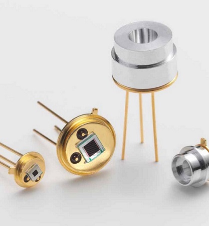
Infrared (IR) sources are micro-machined, electrically modulated thermal infrared emitters featuring true black body
radiation characteristics, low power consumption, high emissivity and a long lifetime. The appropriate design is based on
a resistive heating element deposited onto a thin dielectric membrane which is suspended on a micro-machined silicon
structure.The sources are packaged in compact cans and are available with protective cap or with reflector. They can be
fitted optionally with Sapphire, CaF₂, BaF₂ or Germanium broadband IR sources are ideally suited for compact IR gas
detection modules where a high emissivity, high reliability and low power consumption are key requirements.
For Gas Measurement
CO, CO₂, VOC, NOx, NH₃, SOx, SF₆, hydrocarbons, humidity, anesthetic agents, refrigerants, breath alcohol
Technology highlights
• True black body radiation (2 to 14 μm)• High emissivity• Fast electrical modulation (no chopper wheel needed)• High modulation depth• High electrical input to optical output efficiency• Low power consumption• Long lifetime• Rugged MEMS design (passed the requirements of IEC 60721-3-7 Class 7M3, except for BaF₂ and CaF₂ (broadband filters)
Applications
• Medical:Capnography, anesthesia gas monitoring, respiration monitoring, pulmonary diagnostics, blood gas analysis• Industrial:Combustible and toxic gas detection, refrigerant monitoring, flame detection, fruit ripening monitoring, SF₆ monitoring,
semi-conductor fabrication
• Automotive:CO₂ automotive refrigerant monitoring, alcohol detection & interlock, cabin air quality• Environmental:Heating, ventilating and air conditioning (HVAC), indoor air quality and VOC monitoring, air quality monitoring
IRS Labkit
Features:
• Faster and easier design-in of Axetris IR Source family EMIRS200 and EMIRS50• Very efficient tool for evaluating the ideal drive mode for achieving the best signal/noise ratio• Quick and easy start-up and measurement within minutes• Includes everything you need
• Simple Graphical User Interface (GUI) based on LabVIEW software• Set and update all drive parameters live from the GUI• Live diagram plots for data display and recording• Visualized drive mode limitations (recommendations)• Export of bitmap and Excel data
• Direct connection to a PC with RS232 protocol and USB• TO socket and connector for external IR source connection• I/O analog interface for detector synchronization and signal evaluation
Labkit Driver Board
IRS Labkit Specification
Broadband filters Option & Optical Emission Vs. Angle
• Complements detector filter• Eliminates background signal and improves S/N ratio• Protects the IR source in harsh environments• Prevents parasitic influence of the sample gas (for tightly sealed broadband filter installation)
Custom Reflector
• Optimization of the emission distribution with Zemax
Reflectors collimate IR radiation on axis. (red: high emission density per area;
blue: low emission density per area).
True black body radiation (wavelength from 2 μm to 14 μm)
High emissivity
• A unique thin film process creates a pure black body structure with emissivity close to 1.
Fast electrical modulation and high modulation depth MEMS technology
• offers the possibility to achieve thin and low-mass membrane with short time constant, enabling IR-source to be modulated at high frequency with high modulation depth.
Driven with a constant voltage square-wave drive and measured with a high speed
broadband detector.
High electrical input power to optical output efficiency
• Due to the black surface, the IR source has excellent electrical to optical conversion efficiency. The black body surface guarantees maximized emissivity while the thin membrane is responsible for optimized heat flux.
Efficiency optimization by heat flux simulation.
Reliability of the MEMS structure• The semiconductor MEMS manufacturing technology guarantees high reliability and quality of the IR sources. In addition to the strict quality control system during wafer-level manufacturing, every single IR source is subjected to a final burn-in and test.
• The Mean Time To Failure (MTTF) for membrane breakage of the IR source is based on a statistical analysis of lifetime data collected from several years of reliability testing. Reliability of the membrane breakage depends greatly on the type of packaging, the electrical input power and the operating mode.
Lifetime reliability plot for IR Sources in modulated mode with 10Hz (EMIRS200),
30Hz (EMIRS50) with a typ. duty cycle of 62% (dashed line) and CW mode (solid line).
Main Measurement Principles:
Non-Dispersive InfraRed (NDIR) principleNon-Dispersive InfraRed spectroscopy utilizes a broadband infrared source covering the entire wavelength spectrum needed to measure a large variety of gases. The specific wavelengths desired to measure the gas(es) of interest are selected with narrow band pass filters. The radiation is absorbed by the gas resulting in a signal decrease which is proportional to the gas concentration inside the sample volume. Thermopiles or pyroelectric detectors are commonly used for this spectroscopy technique.
Photo-Acoustic Spectroscopy (PAS) principle
When infrared radiation is absorbed, the absorbing gas is heated. This heating causes a thermal expansion which, in turn, is responsible for a pressure increase in the sample volume. When the radiation is switched off, the gas cools down and the pressure decreases accordingly. With a pulsed IR source, a pressure wave e.g. soundwave is created which can be detected with a microphone. The higher the concentration of the gas of interest (appropriate wavelength has to be chosen with filters), the higher the signal. PAS is not limited to gases but can also be applied to liquids and solids.
Attenuated Total Reflectance (ATR) principleWhen radiation is totally reflected from an interface a small part of it will be transmitted into the adjacent medium. This evanescent wave experiences an exponential decay with penetration depths in the order of the wavelength. The amount of light that is coupled into this evanescent wave depends on the difference of refractive indices of the two adjacent media. In ATR spectroscopy, a crystal made of a high refractive index material serves as the light guiding medium. The sample, usually a liquid, is brought into contact so that the evanescent wave can interact with it. The appropriate wavelength is chosen with a narrow band pass filter. Depending on the state or quality of the sample, more or less light is coupled out and the signal on the detector then changes accordingly. Line arrays of thermopiles or pyroelectric detectors are frequently applied in these setups.
Product Portfolio & Brochures
English: IR LED Chip
产品册中文: IR LED Chip
Electrical/Optical Characteristics
Drawings
EMIRS200_AT02V_BR060_Series
EMIRS200_AT01T_BR080
We are here for you!
Don't have time to search the products one by one? No worries. you can download the full range of SIMTRUM Product Line Cards.
Click it now.
Want to stay closer to the Market Dynamics and Technological Developments? Just take 5 seconds to Sign In as a member of SIMTRUM, we will bring you the most up-to-date news.
(Sign in button on the top right of the screen).
Company
Light Analysis
Microscope
Light Sources
Imaging
Optics