Setup-Guide: Femtosecond pump-probe transient absorption spectroscopy
+ultrafast spectroscopy +pump-probe +transient absorption +data acquisition +harmonic generation +continuum white light module +delay stage
Author:
Majid Panahandeh (PhD NTU 2014)
At a glance: • Knowledge article • Method •Setup
Ultrafast transient absorption (reflectance) spectroscopy is a technique developed to study dynamics and evolution of excited states on the sub-picosecond timescales in various photo-sensitive chemicals (i.e. inorganic semiconductors, organic compounds, and biological systems). This technique is a non-contact measurement for carriers that can be generated in the absence of an external electric field. Moreover; this technique has widely been used for studying the highly resistive materials since it is difficult to inject carriers from metal contacts into the materials.
This application note will discuss fundamental of this technique, its application, experimental setup and required optical components. It also shed light on measurement in the reflection geometry.
Contents
Application of Pump-Probe Specroscopy
In semiconductors and oxide materials, the timescales for transient processes such as carrier-carrier scattering, intervalley scattering, and carrier-optical phonon scattering are usually in the order of few to hundreds of femtoseconds. In contrast, the slower optical processes such as carrier diffusion and inter-sub-band scattering take place within one picosecond or less. Other transient processes such as carrier-acoustic phonon scattering, hot carrier-phonon interaction and carrier recombination, typically take place at a longer timescale, 10 to 100 ps or even more. You may refer to our tutorial, Jablonski diagram, for more details. This technique is being used to provide information about elementary processes, which take place in semiconductors and oxide materials. Some of the specific information that can be obtained are:
-Carrier photogeneration
-Relaxation paths
-Hot charge transfer states
-Hybridization of localised and delocalised states
Principle of photoinduced absorption spectroscopy
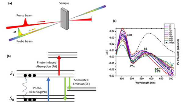
This technique uses two ultra-short pulses, namely pump and probe, to create and probe the excited states. Since excited states species are typically short-lived, we need short (~100 fs) duration pump and probe pulses to get the temporal evolution of excited-states. In this technique, an ultra-short (~100 fs) pump pulse is used to photoexcite the material and a low-intensity, ultra-short white probe pulse is used to monitor absorption changes in the material, specifically kinetics of excited states after excitations. By delaying probe pulse respected to pump pulse, we can measure the evolution of photogenerated carriers within different delay times from a few femtoseconds (fs) to a few nanoseconds. Figure 1 shows the working principle of the transient pump-probe technique. Typically, photoexcited carriers can go through different relaxation pathways before returning to the initial thermal equilibrium states.
In general, photoinduced absorption is measured by monitoring the change in transmittance of a weak probe beam induced by a stronger pump beam. For small values of the differential transmittance, ΔT/T, and uniform excitation, photoinduced absorption is defined as:

Where T is the transmission of the probe
beam when the pump is on while T0 is
the transmission of probe beam when the pump pulse is blocked. In other word,
by measuring the difference of the light transmission with and without pumping,
one can determine the difference in light absorption (Δα) between the excited sample and that in equilibrium. Through
varying the delay time and recording the ΔT at each delay time, the temporal profile of the dynamics
can be gained (see Figure 1c). By choosing different wavelengths λ, the
spectral profile of the dynamics can also be acquired. The bandwidth of the
pump pulse should be narrow in order to enable selective excitation of an
optical transition.

Figure 1: Schematics of pump probe technique. (a) Principle of pump probe
technique, which uses a narrow band pump and a broadband probe beam. (b) Energy
levels of a single molecule (due to the absorption of the pump pulse,
electronic transitions occur from the ground state (S0) to upper excited
states) (c) a typical transient absorption spectra measured by SIMTRUM R &
D team.
Methodology
Mathematical formalisms
When light hits an object, different phenomena may happen, resulting in some ratio of incident light to be reflected, refracted, absorbed, or transmitted. If we assume that scattering is negligible, the total incident intensity is conserved as:
| 
| (1) |
where 10, Ir, It, and Ia are incoming, reflected, transmitted and absorbed light intensity respectively. In general, the transmission coefficient of a thin film with thickness d, refractive index of n, absorption cofficient a, and reflection coefficient R, is given by:
| 
| (2) |
where δ=2πnd/λ is the optical phase shifting per
pass.
Similarly, the reflection coefficient R for an
incident electromagnetic plane beam through a film with a
thickness d and absorption coefficienta, may be described by:
| 
| (3) |
where n and k are the real and
imaginary parts of the complex refractive index (ñ=n+ik). k can be
directly related to the absorption coefficient through:
| 
| (4) |
In equation 2, we can safely neglect the
interference effects since we assume that the thickness of the spin-cast film
is much lower than the incident wavelength (d<<λ). In addition, due to
the roughness of the spin-cast film, the interference effects are expected to
cancel out. Therefore, according to Lambert-Beer law the transmission of the
probe light can be rewritten as:
| 
| (5) |
As a first approximation, we
assume R<<1 then (1-R)2=1, therefore, the transmitted
probe light through the sample can be simplified as:
| 
| (6) |
Upon absorption of light, contributions of absorption
bands due to the photoexcitation will alter absorption coefficient. Therefore,
| 
| (7) |
The absorption coefficient is defined as product of
the population of photoexcitations and a cross section of those photoexcitation
as:
| 
| (8) |
The normalized differential change in transmission
can be expressed as density of photoexcitation and their optical cross section:
| 
| (9) |
where s is the optical cross-section of the photoexcited
species, and ne is the density of photoexcitation. Equation 9
implies that in the case of very weak reflectance, modulation transmittance is
dominated by the change in the absorption coefficient.
In the above-mentioned derivation, we assumed there
is a feeble reflection on the surface of the film that can be neglected. Also,
we assumed that the reflection coefficient is the same for the back and front
sides of the sample. Now we consider that reflection on the surface of the film
cannot be neglected. By neglecting the multiple reflections, the derivation of
equation 5 with respect to modulation filed F can be written as:
| 
| (10) |
Dividing by the unperturbed instensity, we obtain:
| 
| (11) |
For normal incidence yields,
| 
| (12) |
Therefore, the modulated of transmittance of a film can be expressed as:
| 
| (13) |
If we assume there is a very weak reflection on the
surface of the film, the first term can be neglected and equation 13 can be
simplified as:
| 
| (14) |
Carrier-induced optical effects cause small changes in
reflection coefficient R. Therefore, modulated reflectance, ∆R, can be
expressed in terms of the complex index of refraction. Since ∆R is very
small, it can be linearly approximated in terms of ∆n and ∆k as:
| 
| (15) |
By using the Fresnel equation for reflectance at
normal incidence, the differential reflectivity is given by
| 
| (16) |
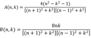
where,
| 
| (17) |
In general, the real and imaginary parts of the
refraction index, ∆n and ∆k are connected through Kramers-Kronig
relations.
| 
| (18) |
Since the extinction coefficient is directly
proportional to the absorption coefficient, the change in the index of refraction,
as a function of frequency, ∆n (ω), can also be expressed in terms of the
change in absorption, ∆a (ω):
| 
| (19) |
By using the Kramers-Kronig relations 17, one can
obtain the change in reflectivity as a function of frequency in terms of the
absorption as:
| 
| (20) |
The relation between ∆n and the ∆a is essential
for the interpretation of the differential reflectivity signal. If we assume
the magnitude of n is much larger than k, in this
case, A (n, k) >> B (n, k). In such instances, the
photoinduced reflectance response is dominated by ∆n rather than
∆k, unlike photoinduced absorption which is dominated by
∆k. Therefore, in this case, the modulated reflectance ∆R/R can
be simplified as:
| 
| (21) |
Experimental setup
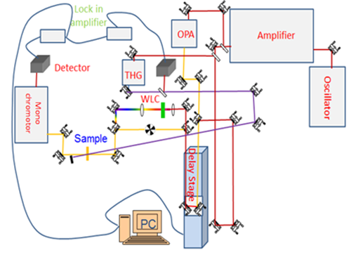
Figure 2 shows the schematic diagram of femtosecond pump-probe transient absorption spectrometer. The setup is comprised of five main parts, which are:
-Excitation state
-White light continuum module
-Delay-stage
-Spectrometer
-Processing software
Excitation Source: In most conventional pump-probe setup, excitation source feeds an optical parametric amplifier (OPA), which allows generating a wide range of pulses from deep-UV to MIR region. Pulses from the OPAs are used as a “pump” to promote a fraction of molecules to excited states.
White Light Continuum Module
The probe pulse is generally white light. The continuum white light can be generated either by Sapphire crystal for Visible to NIR or CaF2 for Nir to MIR region. Laser pulse width, beam shape and power play a crucial role in WLC generation and its stability. Therefore, pulse width, beam shape and power were optimized by adjusting the compressor of the amplifier, iris and ND filter, respectively, to stabilize the WLC.
Delay Stage
A translation stage is used to generate temporal delay between pump and probe, which allows one to monitor the temporal dynamics of our system from a few 10s femtoseconds to a few nanoseconds.
Spectrometer
TA measurements can be performed using a monochromator coupled to a-Si photodiode, cooled PMT or a CCD camera.

Figure 2: Proposed experimental setup
Editor’s Notebook
Components for consideration
White Light Module
SIMTRUM offers WLC modules that can be easily mounted in your pump-probe setup. The white light continuum (WLC) is a third-order non-linear phenomenon was generated by tight focusing of the laser beam in a non-linear medium. IN our module, visible WLC is generated by focusing the 800 nm beam into a 2 mm thick sapphire crystal and Laser power is adjusted by ND filters and residual of 800 nm laser in WLC is blocked by a notch filter. The final output is a collimated white-light continuum. Our NIR module generates WLC by focusing NIR nm laser beam into a 4 mm thick yttrium aluminium garnet (YAG) crystal. The residue of NIR laser from the NIR WLC will be filtered by a short-pass Dichroic mirror.
Spatial Filter Module
SIMTRUM offers an innovative solution for generating perfect gaussian beam. Our spatial filter removes higher-order modes.
Second & Third Harmonic Generation
In our module, the SH is generated using a type-1 BBO crystal (phase-matching angle 29.20) while the TH is generated by the sum-frequency generation of 400 nm and 800 nm in a type-2 BBO crystal (phase-matching angle 55.50). A neutral density (ND) filters will be used for adjusting pump laser power.
Technical Tips
The probe beam is being used
to detect the perturbation effect by the pump beam in the sample. It should be
much weaker than the pump beam to avoid multi-photon/multistep excitation
during probing.
The pump beam is chopped at a specific frequency
(usually add number is chosen) and referenced to the lock-in amplifier. Optical
nonlinearities effects (i.e. bimolecular processes) will be minimized by
setting the pump power density to a value well below 100 µJ/cm2 per pulse.
Reflection geometry for opaque sample
Transient absorption measurements either in the
transmission or reflection geometry can provide information on the dynamics of
the nonlinear photoexcitation, which is fundamental to understanding the
primary events taking place in the excited state. However, transient
reflectance spectroscopy is more sensitive to the surface inhomogeneity.
Besides, due to a limited penetration depth of the probe beam in the absorbing
medium, the changes in the reflection signal due to the absorption modulation
by the pump pulse are much smaller as compared to the change in the
transmission signal. In reflection geometries, probe light is reflected off
from sample, then collected and monitored using a spectrograph coupled with
detector configuration with lock-in or CCD detection. Within this experimental
configuration, the differential signal obtained by amplitude modulation of the
pump beam effectively gauges the photoinduced transient reflectance. It should
be taken in the account that interpretation of data for thin film samples in
reflection geometry is more complicated due to double-pass backscattering at
the interface of thin film and substrate.
Simtrum is active in the Photonics field and welcomes
any emails for discussions, questions or implementation. We are based in
Singapore (+8GMT) and available via Phone or Email. We are especially
interested in customised solutions not commercially available.
Consultation
With over a combined 12 years of experience in the field, Simtrum’s R&D team has developed tens of spectroscopic setups with unique capabilities that are not available in commercial instruments. Our project team is focused on practical and elegant solutions. Please contact us If you need any enquiries about femtosecond transient absorption spectroscopy and setting up experiments.