With the advancement of science and technology, more and more applications of laser technology are involved in basic research in the fields of biology, medicine, chemistry, and experimental method. However, in practice, the difference between the spectroscopic effect and the application conditions, and the confusion about the spectroscopic effect often result in wasted experiment costs and time.
From the polarization state of the output light source, the spectroscopic device can be divided into two categories: polarization splitting and energy splitting.
1. Polarization splitting
Polarization splitting, as the name suggests, is to separate the output light of the light source in the form of linearly polarized light. The light beam passing through it will decompose into two linear polarizations whose vibration directions are perpendicular to each other, that is, the polarization of P light and S light, which is often said in optics. Limited by the device itself, generally transmitted beam will get linearly polarized light with an extinction ratio effect better than 30 dB or even 50 dB, but at the same time, its reflected polarization is generally around 20 dB or even lower.

Figure 1. Non-Polarization Beamsplitter Cube
2. Energy splitting
Energy splitting is slightly more complicated than polarization splitting. Although this device is used to distinguish the beam energy according to the proportion of the corresponding demand in the application, in actual experiments, according to the polarization characteristics of its light source, it can be refined into three beam splitters, which are ordinary energy beam splitters and polarization-designed energy splitter and depolarized energy splitter.
The following is a comparison and analysis of these three energy splitting devices so that you can be handier when selecting devices.

1.Ordinary energy splitter
It is suitable for light sources that need to be split to output at random polarization, that is, the output light does not have any specific vibration direction. It simply splits the overall energy of the light source in proportion to the demand. When this device is applied to a light source with some linearly polarized light or a single linearly polarized light output, its split ratio will appear to be a random ratio different from the design requirements.
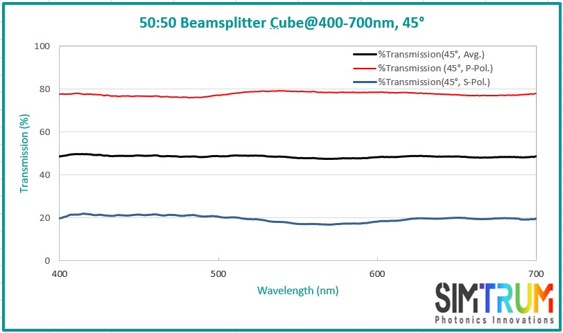
Figure 3. Example T/R=50%: 50%@400-700nm-45°, the design of the splitting effect is a black line, and the red and blue lines are tested for the transmission effect of the device corresponding to P light and S light. Design transmission effect Tavg=(Tp+Ts)/2.
2. Energy splitter designed for polarization
It can be seen from the name that this type of device is different from the scope of application of ordinary energy splitter. It is only suitable for light sources with linearly polarized P light or S light output, and the corresponding splitting ratio is completely designed for the linear polarization state of the light source. When it is used under other polarization conditions, its splitting effect will also appear in a random ratio different from the design value.

Figure 4. Example Tp/Rp=50%: 50%@400-700nm-45°, design P beam splitting effect see black line, at this time S light splitting effect cannot be determined randomly.
3. Depolarization energy splitter
It is a device with high applicability, which can fully cover the application scope and effect requirements of the above two devices. On the premise of meeting the required splitting ratio, it can be applied to random polarized light sources, linear polarized light sources, and some linear polarized light sources. Any light beam with a polarization effect will not affect its design split ratio. However, compared with the above two devices, the price and cost are much higher, and its prismatic structure will absorb 10% of the energy of the designed spectrum. However, you can choose to eliminate the polarized beam splitter structure without this concern. According to the figure below, it can be seen that the red and blue test curves of the P and S light transmission of the device are very close to the black test curve of the average value of the device, that is, the device design band Tp≈Ts≈Tavg.
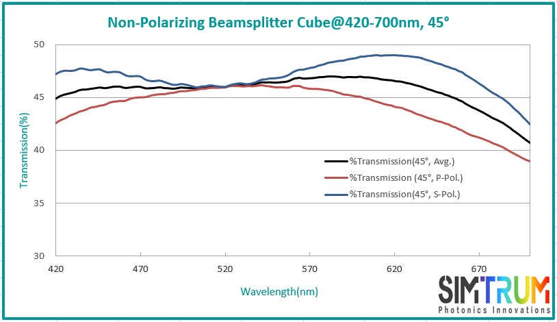
Figure 5(a). A depolarizing beam splitter prism with energy absorption, T/R=45%: 45%@420-700nm-45°, |Rs-Rp|<6%
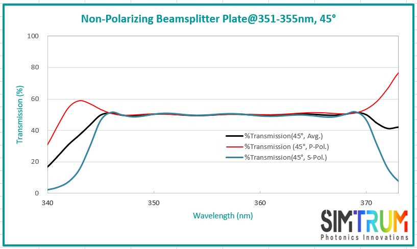
Figure 5(b). A depolarizing beam splitter without energy absorption, T/R=50%: 50%@351-355nm-45°, |Rs-Rp|<5%
Note: The selection of wavelengths in the two example diagrams also reflects that the chip depolarization device is not suitable for designing and processing wide-spectrum bandwidth, it is only suitable for processing narrow-bandwidth devices.
Warm reminder: When choosing a splitting device, users need to clearly define the purpose of beam splitting and the polarization of the light source, to achieve accurate selection, suitable for use, and cost-effective products.