Abstract: The lens is the most commonly used optical element besides the plane mirror. As a transmissive element, its main function is to change the focused (divergent) state of the light beam and then to achieve imaging or beam reduction (expansion). This article focuses on the use of the lens in the optical path, hoping to give some help to the optical path regulator.
In life, the most commonly used lens is our eyes. As shown in Figure 1, the human eye is like a camera, the lens is equivalent to the lens of the camera, and the retina is equivalent to the film of the camera. The difference is that the lens is an automatic zoom lens that can make objects, which are from 25cm in front of the eye to a long-distance, imaging onto the retina. Prolonged improper use of the eyes can cause tight muscles in the eyes that can lead to myopia. As shown in ① in Figure 2, the lens gradually thickens, the focal length of the lens becomes smaller, and distant objects are imaged in front of the retina. Hence, the image received on the retina is unclear. However, the lens of myopia glasses is a concave mirror, as shown in ③ in Figure 2. Using it, you can image distant objects on the retina and see a clear image. With age, the lens gradually loses its elasticity that can lead to presbyopia. As shown in ② in Figure 2, as the lens loses its adjustment function, a lens that can image distant objects to the retina will image nearby objects to the back of the retina. The lens of the reading glasses is convex, as shown in ④ in Figure 2, which can be used to image nearby objects on the retina and see a clear image.
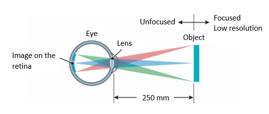
Figure 1. Human eye imaging
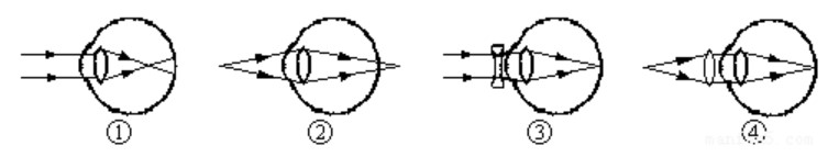
Figure 2 Schematic diagram of myopia and presbyopia. ① Imaging of myopia; ② Imaging of presbyopia; ③ Imaging after using myopia glasses; ④ Imaging after using presbyopia glasses
Outside of life, lenses also play an indispensable role in optical experiments.
Before using the lens, we should determine the focal length of the lens firstly. Generally, the lens we get will be marked with the focal length, but if it is found that the focus of a lens on the beam (here only for the convex lens) does not match the actual label in the experiment, then the lens measurement is required. Only the simplest imaging method is introduced here: we can take a piece of white paper under the fluorescent lamp, and then move the lens away from the white paper from the position close to the white paper. when the image of the fluorescent lamp becomes clear during the observation process, the distance of the lens and the white paper is roughly the focal length of the lens. The advanced methods of measuring lenses include the Range image method and the Displacement method. For specific experimental steps, please refer to the physics experiment "Focal Length Measurement of Thin Lens" in university.
Secondly, the surface shape of both sides of the lens should be judged. Plano-concave or plano-convex lenses are commonly used. Under fluorescent lamps, the angle of the lens is rotated so that the eye can observe the image of the fluorescent lamp reflected on the lens surface. Then we can tilt the angle of the lens. If the shape of the image reflected by the fluorescent lamp from the lens edge to the center of the lens is not significantly changed, the surface is flat; if the image of the fluorescent lamp will be enlarged or reduced, the surface is convex or Concave. Pay attention to distinguish the reflected images on the upper and lower surfaces of the lens by the reflected light intensity. For high-energy laser systems, the convex surface should face the light when placing the lens to prevent the reflected light from the inner or outer surface from converging and damaging the front optical components. In the laboratory, the lens is used on the following occasions: focused beam; laser beam contraction (expansion) or collimation; laser image transmission.
1. Focused beam
In many experiments, we need to focus the beam on a certain object point, but in most cases, it is inconvenient to directly observe the focus of the beam at that point. For the convenience of observation, you can place a sharp split at a distance d in front of the object point and place a CCD camera at the same distance d in the direction of the reflected light. We can fix the lens on the translation stage and observe the focus of the light spot at the CCD camera to determine the moving direction of the translation stage so that the light spot at the object point is focused to a minimum. It should be noted that in this operation, the two surfaces of the split will be reflected against the incident light, and the two reflected lights will be at an angle. Considering that the split is very thin, the strong light reflected from the front surface can be used as a reference. From the spatial perspective, we can take one beam of the two reflected lights near the tip of the split.
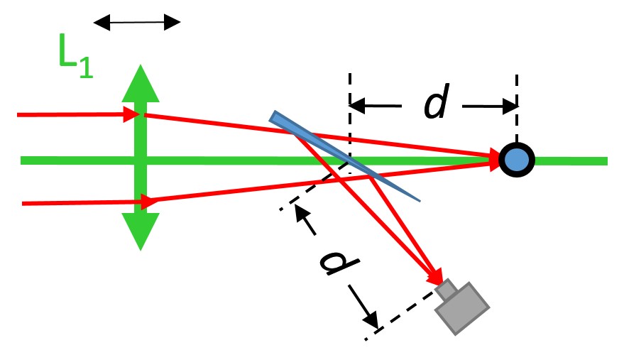
Figure 3. Observation of focused light spot
2. Laser beam contraction (expansion) or collimation
In the laboratory, it is sometimes necessary to reduce (or expand) the laser beam. In this case, a combination of a convex lens (focal length is positive, which is also known as a positive lens) and a concave lens (focal length is negative, which is also known as a negative lens) is required to achieve laser beam contraction (or expansion).
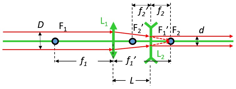
Figure 4. The principle of laser beam contraction
Figure 4 shows the principle of laser beam contraction. L1 is a positive lens, and L2 is a negative lens. The diameter of the light beam incident on the lens group is D, and the diameter of the exit is d. You can choose the ratio of the focal length of the two lenses according to the beam contraction ratio, and the distance between the two lenses is when placed. If you want to expand the beam, you can place the negative lens before the positive lens to achieve beam expansion.
In the experiment, due to the incident light is not necessarily collimated, the distance between the two lenses will not strictly follow the formula, but the difference will not be too large. You can first place it according to the distance L, and place the lens L2 on the translation stage. You can move the translation stage, and measure whether the spot sizes are equal in the near and far fields of the outgoing light direction (you can use a ruler to measure or place a sharp split and use a CCD to monitor in real-time). If it is observed that the outgoing light is divergent, it means that the focal distance of the negative lens L2 and the positive lens L1 is close, and it is necessary to move L2 close to L1; if it is observed that the outgoing light is convergent, move L2 away from L1.
According to the above description, this method can also be used for beam collimation, the ratio of positive and negative lenses is selected to be close to 1:1, and the output light is adjusted to be parallel light according to the above description. Pay attention to choosing lens pairs with larger focal lengths (such as positive and negative lenses with focal lengths of +500mm and -450mm), so that the state change of the emitted light is not particularly sensitive to the change of the distance between the two lenses, and it is easy to adjust.
Of course, some people will ask why it is not possible to use the combination of the two positive lenses in Figure 5 for beam contraction. In fact, it is not impossible to use this method. In some cases, it must be reduced (expanded) in the manner of FIG. 5, such as the image transmission system to be mentioned below. There are two reasons for choosing the method of Figure 4: under the same beam contraction ratio (beam expansion ratio), the distance between the two lenses in Figure 4 is smaller than that in Figure 5, which can save a lot of space; for some strong laser system, the focus cannot appear in the optical path, and a vacuum tube needs to be added between L1 and L2 to avoid the laser filament in the air (that is, a nonlinear effect in the air, which will seriously affect the output beam quality and spot uniformity) ). It increases the complexity of the optical path.
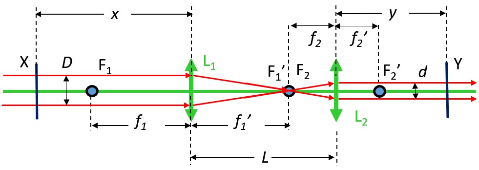
Figure 5. The principle of laser image transmission
3. Laser image transmission
It is an assumption to treat laser light as parallel light. In practice, laser light transmits in the form of a Gaussian beam. The laser transmits in a certain divergence angle, and the image in the near field will always be better than the image in the far-field. For some strong laser systems, it is often necessary to transfer the image from the near field to the far-field in experiments. The problem is, in Fig. 5, the incident light should be beam-reduced, and the image should be image-reduced on the X plane to the Y plane. What should we do?
We assume that the beam is still reduced from the diameter D to the diameter d. According to the previous section, the ratio of the focal lengths of the two positive lenses is selected. The distance between the two lenses, while the distance between L1 and the X plane is x, and the distance between L2 and the Y plane is y. It can be calculated according to the imaging formula. Knowing the distance between the X and Y planes and determining the focal length of a lens, all parameters can be obtained. The special case is a 1:1 image transmission system. In this case, the focal lengths of the two lenses are equal and equal to 1/4 of the spacing distance between the X and Y planes. The spacing distance between the two lenses is double focal length. The entire group of lens can be moved freely on the X and Y planes.
The above part is a theoretical guide, there are still some details to be paid attention to when using the lens:
1. The light must hit the center of the lens, and it must be normal incidence into the lens, otherwise, it will affect the direction of light transmission or lead to astigmatism. To avoid such problems, you can deal with them as follows (note that the following steps are all carried out under low light):
(1) Ensure that the incident light transmits along with the same height, and record the central position of the incident light at a distance (or observe with CCD), and draw the direction of light transmission on the optical platform;
(2) Placing the lens in the light path, the concave surface is facing the light. By adjusting the up, down, left and right positions of the lens, the center of the light passing through the lens are consistent with the previous position so that the incident light is guaranteed to pass through the lens center;
(3) You can adjust the pitch position of the lens mounting frame, so that the light reflected by the concave surface is the same height as the incident light, thus ensuring the normal incidence of the sagittal plane (the surface perpendicular to the optical platform);
(4) You can rotate the lens 180 degrees to make the convex surface meet the light and adjust the incident light again through the center of the lens. Then you can turn the lens to visually and check the lens surface perpendicular to the line of the platform so that the meridian plane (parallel to the surface of the optical platform) is generally ensured normal incidence. In practice, it is easier to handle the incident light through the center of the lens, but it is more difficult to ensure that the incident light is incident on the lens. Fortunately, the effect of the latter on astigmatism is not very serious. If there is no special requirement, it can be adjusted according to the above method. If it is necessary to focus the light spot on the surface of the object in strong-field physics, you need to use the CCD to observe the effect of the tilt of the lens on the astigmatism of the focused light spot, and fine-tune the lens level and tilt angle accordingly.
2. The material of the lens will affect the transmittance of light of different wavelengths.
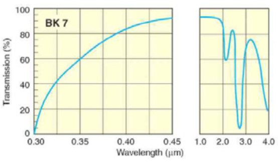
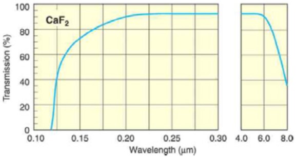
Figure 6. Transmission curves of BK7 and CaF2 glass
The commonly used lens material is BK7 (K9) glass, which has a high transmittance for light between 500nm-1μm; fused silica glass (JGS1) has excellent transmittance in the ultraviolet band, whose transmittance in the visible band is very high. And JGS1 glass, which is suitable for high-energy laser systems, has a higher damage threshold than BK7 glass; CaF2 lens has a very high transmittance for ultraviolet and infrared, but the price is more expensive, and the coefficient of thermal expansion is large, which requires experimental environment Higher.
3. The same lens, due to the different refractive index of light of different wavelengths, will introduce spherical aberration and dispersion to the incident polychromatic light. To solve this problem, a concave (convex) mirror can be used instead of a lens: since there is no material dispersion, the incident light can be focused (divergent) without spherical aberration and dispersion. However, it must be incident at a small angle when used, otherwise, serious astigmatism will occur.
The above mentioned are just the application of the lens in the dimming circuit. More broadly, information optics uses a lens as a component of phase conversion, while applied optics realizes the most practical optical system that meets imaging requirements by designing a combination of lenses, and so on. The lens, as one of the oldest optical components, still shines in various modern disciplines.